אין מוצרים בסל הקניות.
אודותינו ואודות הקהילה

חנות אלקטרוניקה למייקרים
מה שיש לנו לשתף בנוגע לציוד האלקטרוניקה שאנחנו מספקים למייקרים

45.00₪ כולל מע"ממשלוח: 2 עד 5 ימי עסקים
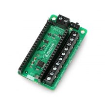
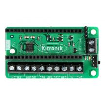
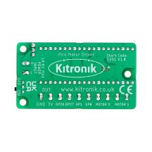
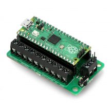
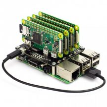
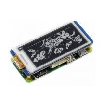
The Robotics Board features 2 Dual H Bridge Motor Driver ICs. These are capable of driving 2 standard motors or 1 stepper motor each, with full forward, reverse, and stop control. There are also 8 servo outputs, capable of driving standard and continuous rotation servos. They can all be controlled by the Pico using the I²C protocol, via a 16 channel driver IC. The IO break out provides connections to all the unused pins on the Pico. The 27 available I/O pins allow other devices, such as sensors or ZIP LEDs, to be added to the board. Power is provided via either a terminal block or servo style connector. out.
קיים במלאי
The supply is then controlled by an on/off power switch to the board and there is also a green LED to indicate when the board has power. The board then produces a regulated 3.3V supply which is fed into the 3 V and GND connections to power the connected Pico. This removes the need to power the Pico separately. The 3 V and GND pins are also broken out on the header, which means external devices can also be powered. To use the robotics board, the Pico should be firmly inserted into the dual row pin socket on the board. Ensure the Pico is inserted with the USB connector at the same end as the power connectors on the robotics board. This will allow access to all of the board functions and each pin is broken.
עדיין אין שאלות למוצר זה.
רספברי פיי

רספברי פיי
רספברי פיי
רספברי פיי
רספברי פיי
רספברי פיי
רספברי פיי
רספברי פיי
פאי 400
רספברי פיי
רספברי פיי
רספברי פיי
רספברי פיי
רספברי פיי

רספברי פיי
רספברי פיי
רספברי פיי
רספברי פיי
רספברי פיי
רספברי פיי
סימנת בפרטי המשלוח איסוף מנקודת שירות, יתכן וחברת השילוח תעדכן את נקודת האיסוף לפי שיקול דעתה במקרה של עומס בנקודת מסירה שבחרתם.
אני מאשר את התנאיםטלפון: 0584998006
כתובת: רחוב הצורן 4 א, נתניה
![]()

סימנת בפרטי המשלוח איסוף עצמי, כמה דברים לדעת לפני:
טלפון: 0584998006
כתובת: רחוב הצורן 4 א, נתניה
![]()