אין מוצרים בסל הקניות.
אודותינו ואודות הקהילה

חנות אלקטרוניקה למייקרים
מה שיש לנו לשתף בנוגע לציוד האלקטרוניקה שאנחנו מספקים למייקרים


185.00₪ כולל מע"מ
משלוח: 2 עד 7 ימי עסקים
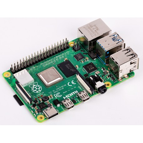
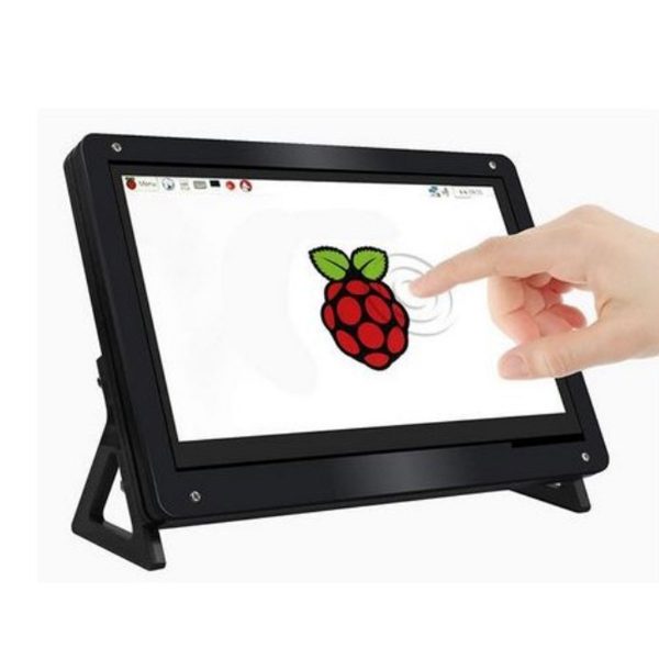
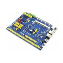
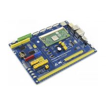
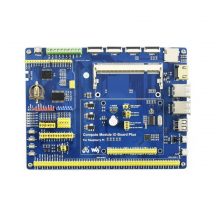
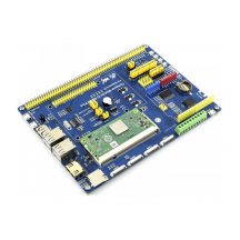
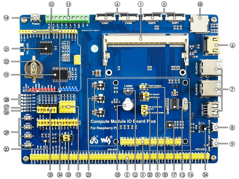
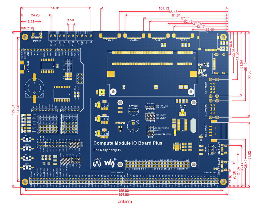
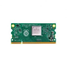
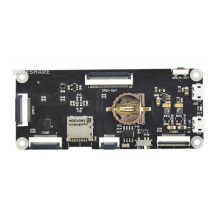
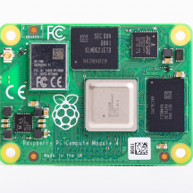
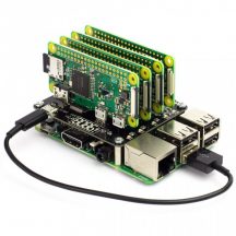
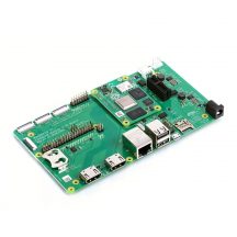
The Compute Module IO Board Plus is a development board which you can plug a Raspberry Pi Compute Module into, and make use of the resources of Pi more flexibly. It is compatible with the Compute Module IO Board V3 from the Raspberry Pi Foundation, along with various common use components.
המלאי אזל
עדיין אין שאלות למוצר זה.

רספברי פיי
רספברי פיי

רספברי פיי
רספברי פיי
רספברי פיי
רספברי פיי
רספברי פיי
רספברי פיי
רספברי פיי
רספברי פיי
רספברי פיי
רספברי פיי
רספברי פיי
רספברי פיי
רספברי פיי
רספברי פיי
רספברי פיי
רספברי פיי
רספברי פיי
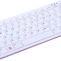
פאי 400
סימנת בפרטי המשלוח איסוף מנקודת שירות, יתכן וחברת השילוח תעדכן את נקודת האיסוף לפי שיקול דעתה במקרה של עומס בנקודת מסירה שבחרתם.
אני מאשר את התנאיםטלפון: 0584998006
כתובת: רחוב הצורן 4 א, נתניה
![]()

סימנת בפרטי המשלוח איסוף עצמי, כמה דברים לדעת לפני:
טלפון: 0584998006
כתובת: רחוב הצורן 4 א, נתניה
![]()